What is the C4 Model? A Zoomable System Diagram!
The Problem
When was the last time you wrote documentation for a system or a function? Did you use any images or diagrams to describe how it works? I'm talking about those activity diagrams, sequence diagrams... to model the workflow of the program. Standardizing the workflow with diagrams has played a significant role in conveying meaning. Because if everyone knows and understands, then...
Usually, diagrams that describe the workflow of a program are sufficient, but only at a functional level. This means that the function works in a certain way, with specific steps and outcomes... If you look closely, it's not much different from the logic of the code. But instead of using a programming language, we describe it through diagrams.
Let's zoom out a bit, and in reality, an information system or a software application is not just a collection of actions, but also a network of interconnected services. This is most evident in the Microservices model, where many small systems work together to form a larger system. And I'm sure that many times, you can't even imagine what's inside, how they're connected.
So, how do we represent this system?
C4 Model
When I recently joined a new work environment, the C4 Model was one of the first things I learned about. It's a diagram that shows the relationships within and outside the system. Specifically, what does the system consist of? How are they connected? From there, it provides a clear view of what you're about to work on.
You might think that drawing a diagram like this is not difficult. Nowadays, there are many tools that support drawing diagrams, from online to offline software. Using simple shapes like rectangles, circles, and diamonds... to represent a service, and then connecting them with arrows, that's it. The truth is, it's not that simple, and I thought so too until I learned about C4. So, what's the point of C4?
It's to provide a common language for reading system models. The shapes we use in the diagram are not wrong, but they're not standardized. Now, imagine asking "Do you have a C4 model?" when taking over a new system. If the answer is "Yes", then everything becomes much easier.
The C4 model is an approach to describing software architecture through 4 levels of detail, making it easy for team members and stakeholders to understand the system's architecture. C4 stands for Context, Container, Component, and Code.
Imagine C4 as a zoomable diagram. The surface is the Context layer - where our system (let's call it A) is at the center, along with external connected systems. When you zoom in on A, you enter the Container layer - describing the containers that A consists of. Containers can be web applications, databases, microservices... each one is like a smaller system (let's call it B). So, within A, there are many B's.
When you zoom in on a B, you enter the Component layer - describing the components within each container. Components are smaller functional parts, like classes, modules, or specific services... let's call it C. And finally, when you zoom in on C, you enter the Code layer - the lowest level of detail, describing the source code structure.
In summary, from A, you get a broad view, and when you zoom in, you see many B's, each B has many C's, and each C has its own source code. This creates a hierarchical diagram, and the deeper you go, the more detailed the system becomes.
To understand the 4 levels better, you should check out The C4 model for visualising software architecture.
From there, you can see that C4 provides a broad view, and if you want to dive deeper into a part, you just need to zoom in, and you'll know what's inside and how they interact. This helps with reading and understanding, making information more transparent.
So, how do you draw a C4 model?
Again, the best way is to check out The C4 model for visualising software architecture. Because this is the website of the person who created C4. But to summarize, just draw each layer!
You need to spend time understanding and identifying the components in each layer. To do this, you should read Frequently asked questions. The FAQs contain most of the cases that new users find difficult.
Usually, the deeper you go into the layers, the more complex and detailed it becomes, which takes a lot of time to complete a full C4 diagram. Not to mention that during development, the source code can change constantly, so it's essential to determine how much detail the project needs. For example, if you just want to provide a broad view in a short time, the Context and Container layers are enough.
C4 has its own language for drawing diagrams, which is structurizr.com. Instead of using drag-and-drop tools to draw shapes, you can write code to create the diagram. This method is a bit extreme at first, but later, editing the diagram becomes easier when you just need to modify the code, and the image is generated automatically.
If you want to see the code you write create a diagram, check out https://www.structurizr.com/dsl.
Before ending this article, I'll practice drawing the C4 model of the 2coffee.dev website, but due to time constraints, I'll stop at the second layer. Mainly to give you an idea of what the system has.
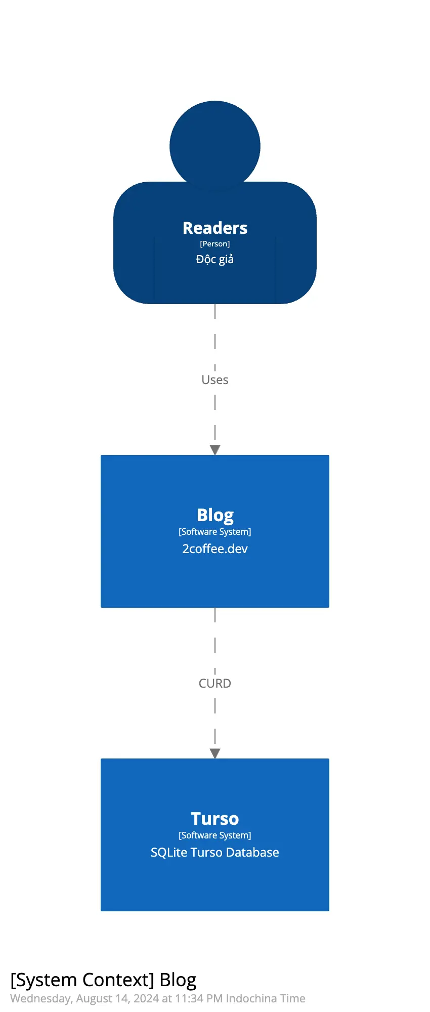
First, let's draw the Context layer, which defines the broad view of the system. The 2coffee.dev system consists of Readers, the 2coffee.dev system itself, and another service called Turso - a serverless database.
workspace {

    model {
        user = person "Readers" "Độc giả"
        softwareSystem = softwareSystem "Blog" "2coffee.dev"
        tursoDB = softwareSystem "Turso" "SQLite Turso Database"

        user -> softwareSystem "Uses"
        softwareSystem -> tursoDB "CURD"
    }

    views {
        systemContext softwareSystem "SystemContext" {
            include *
            autoLayout
        }

        styles {
            element "Person" {
                color #ffffff
                background #08427b
                fontSize 22
                shape Person
            }
            element "Software System" {
                background #1168bd
                color #ffffff
            }
        }
    }
}
The code above generates the following image:
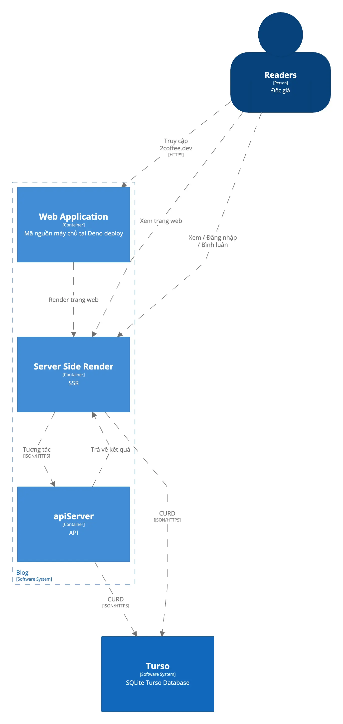
The second layer is the Container layer, which defines the components within the system. 2coffee.dev uses Fresh - a framework that works in a Server-Side Render mode and can also write APIs. So, the main containers are Web Application (the main source code), Server-Side Render, and API Server.
workspace {

    model {
        user = person "Readers" "Độc giả"
        softwareSystem = softwareSystem "Blog" "2coffee.dev" {
            webApplication = container "Web Application" "Mã nguồn máy chủ tại Deno deploy"
            serverSideRender = container "Server Side Render" "SSR"
            apiServer = container "apiServer" "API"
        }
        tursoDB = softwareSystem "Turso" "SQLite Turso Database"

        user -> softwareSystem "Uses"
        softwareSystem -> tursoDB "CURD"

        # relationships to/from containers
        user -> webApplication "Truy cập 2coffee.dev" "HTTPS"
        user -> serverSideRender "Xem trang web"
        webApplication -> serverSideRender "Render trang web"
        user -> serverSideRender "Xem / Đăng nhập / Bình luân"
        serverSideRender -> apiServer "Tương tác" "JSON/HTTPS"
        apiServer -> serverSideRender "Trả về kết quả"
        serverSideRender -> tursoDB "CURD" "JSON/HTTPS"
        apiServer -> tursoDB "CURD" "JSON/HTTPS"
    }

    views {
        systemContext softwareSystem "SystemContext" {
            include *
            autoLayout
        }

        container softwareSystem "Containers" {
            include *
            autoLayout
        }

        component webApplication "Components" {
            include *
            autoLayout
        }

        styles {
            element "Person" {
                color #ffffff
                background #08427b
                fontSize 22
                shape Person
            }
            element "Software System" {
                background #1168bd
                color #ffffff
            }
            element "Container" {
                background #438dd5
                color #ffffff
            }
        }
    }

}
The generated diagram looks like this:
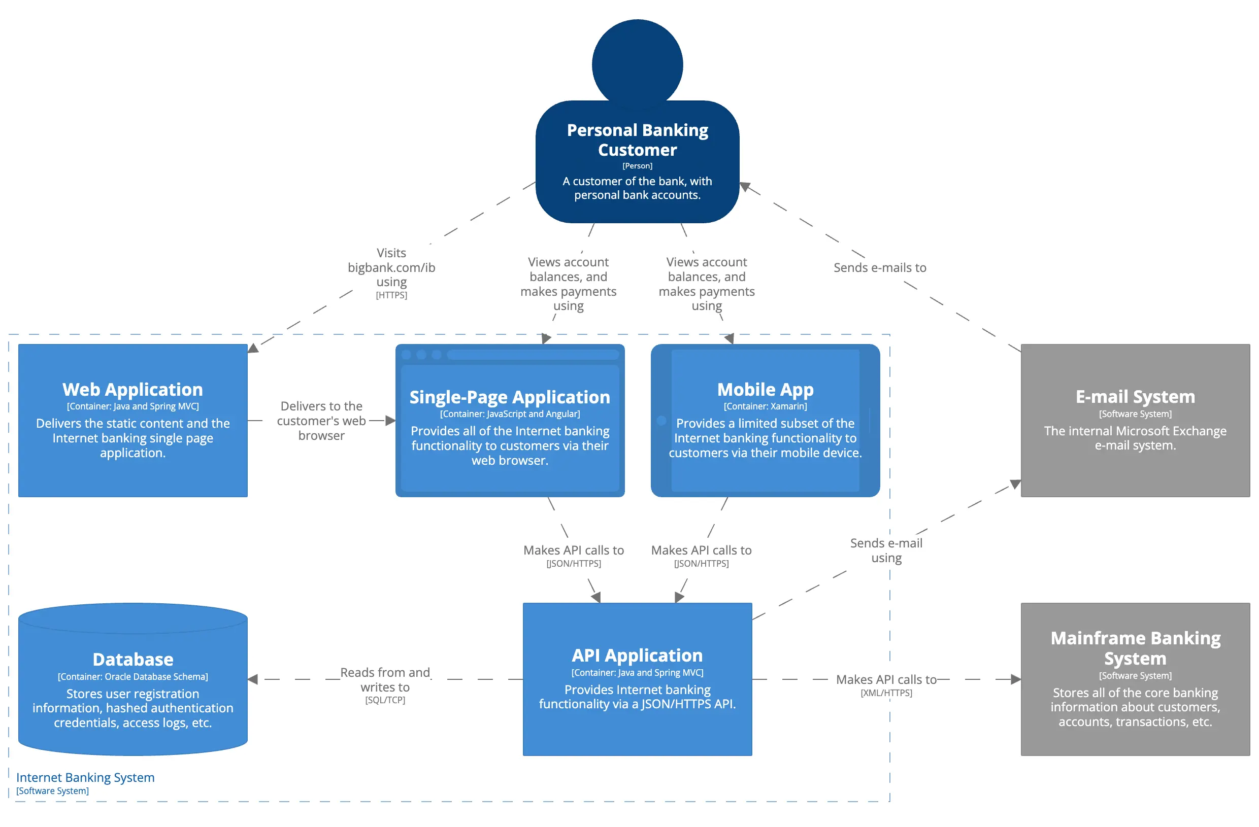
Learning the syntax of Structurizr is relatively quick because it has many examples at Big Bank plc - Internet Banking System. The difficult part is breaking down the system and identifying the components in each layer, along with the level of detail for each layer.